
So many pieces. So many parts. So much testing. So many changes.
Board Design:
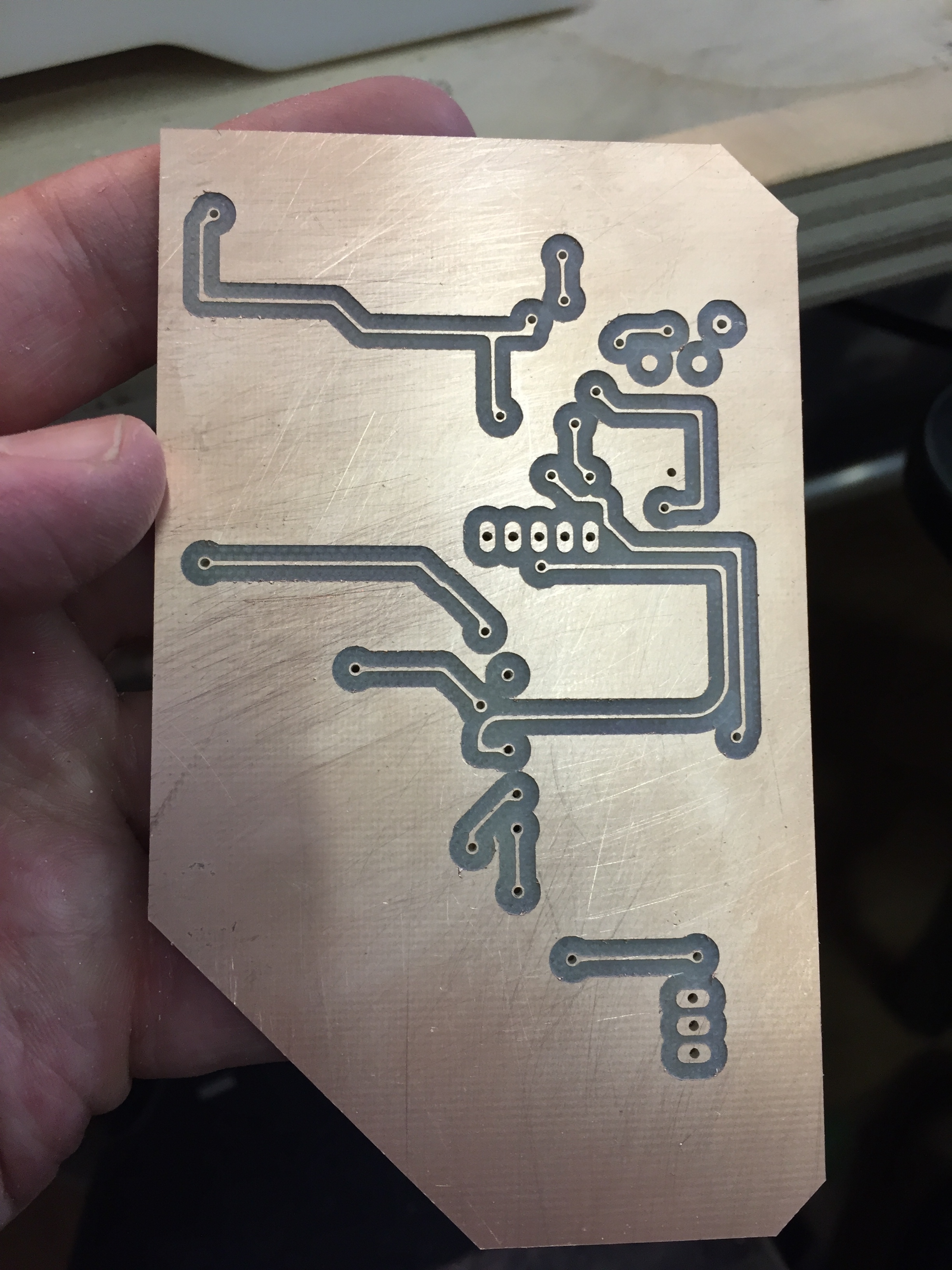
(1)

First board design - look at that rats next ughhh … thanks for the help Andy!
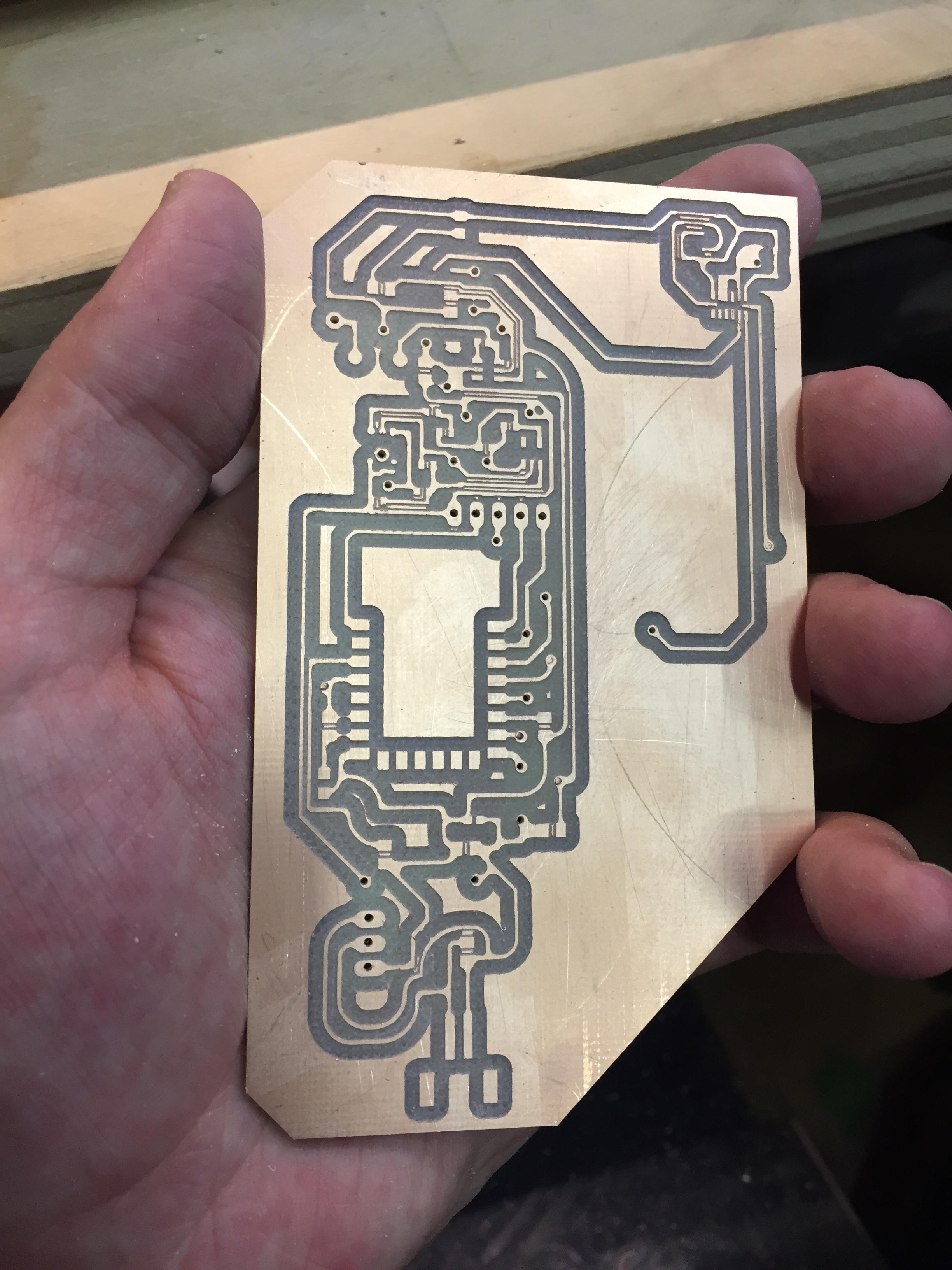
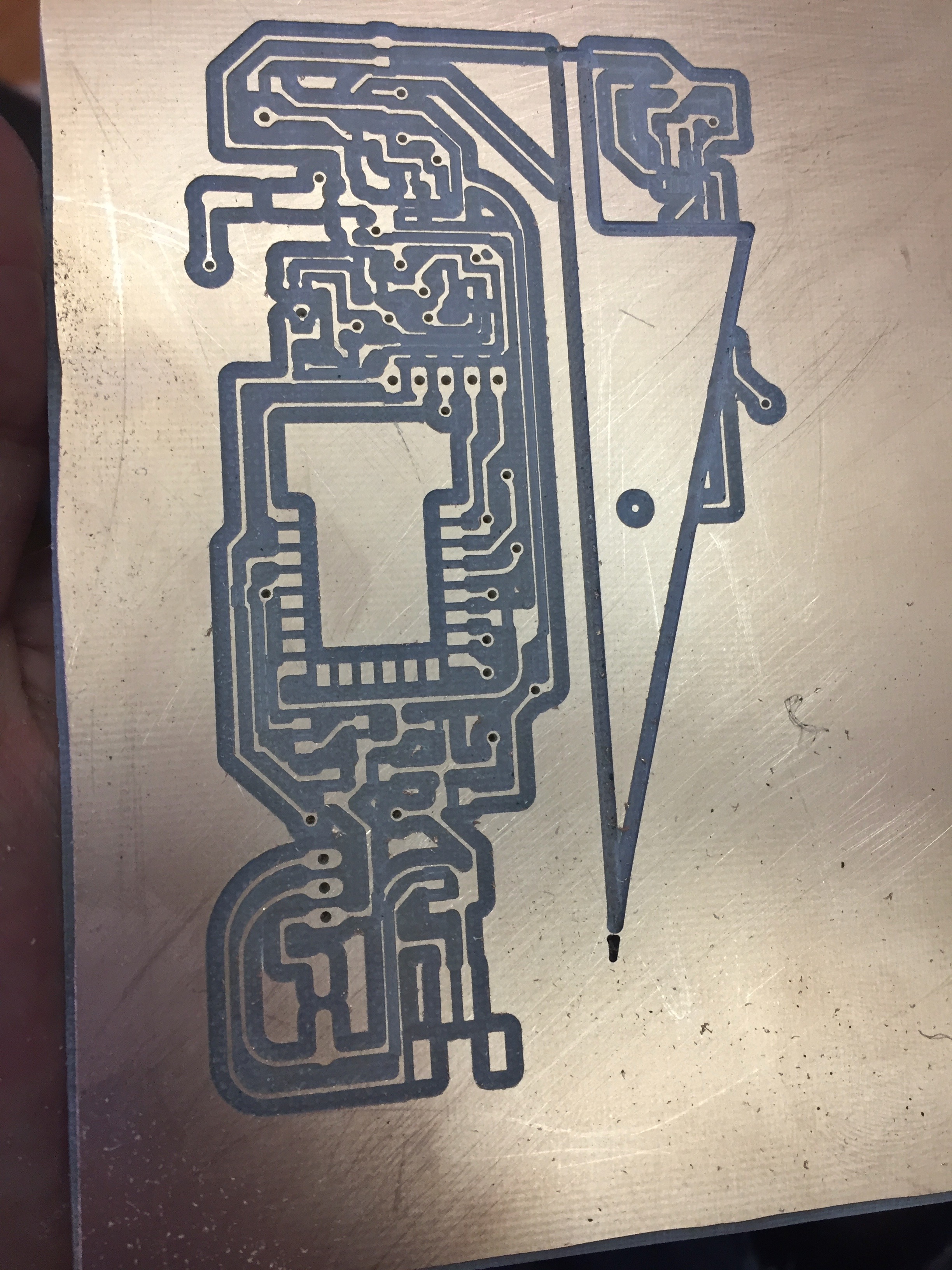
(2)
Final design, accelerometer will be cut from this board and placed somewhere else - it was too long to fit on the board in a straight line
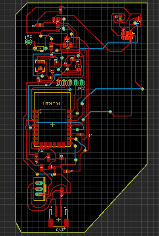
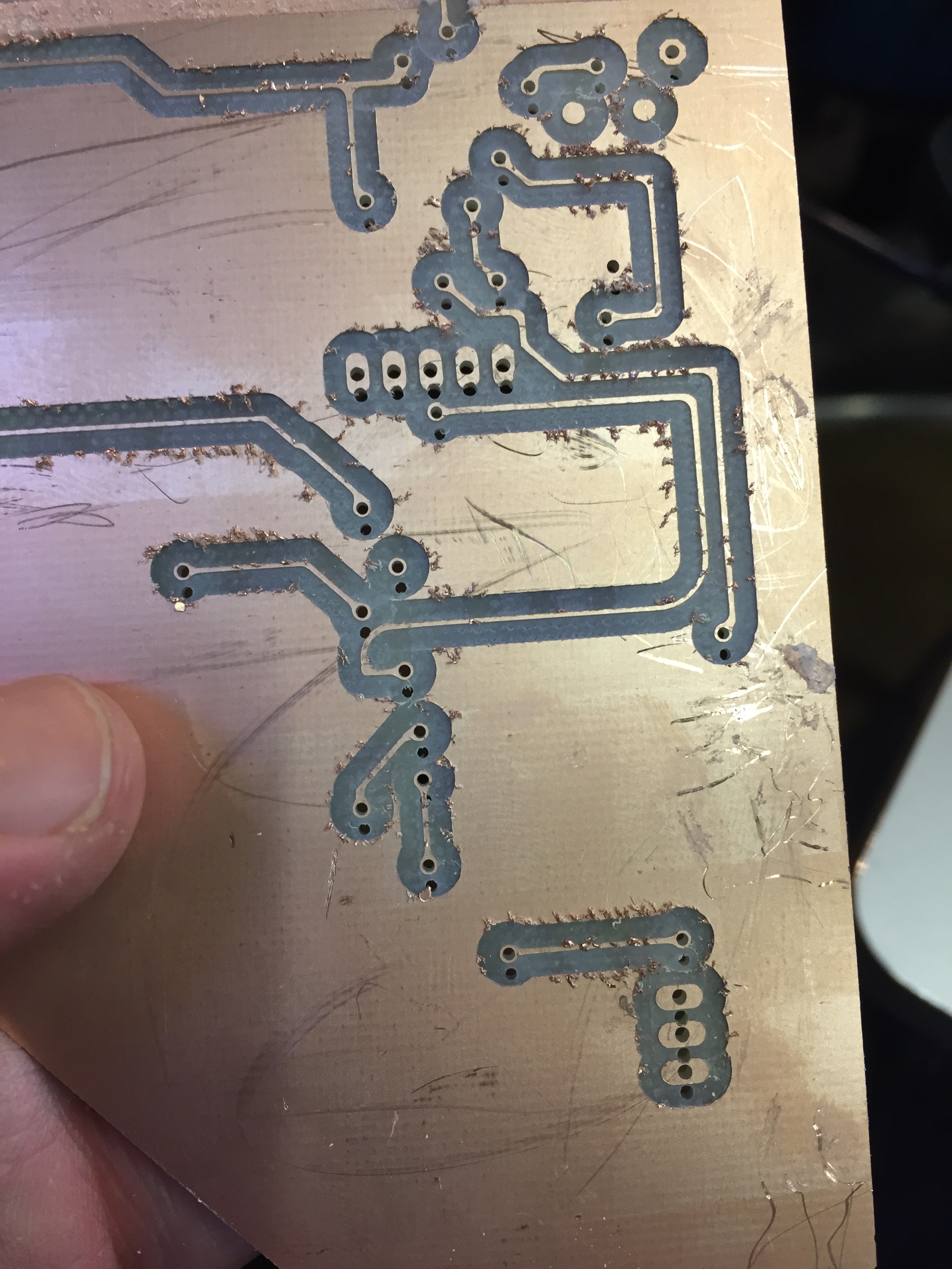
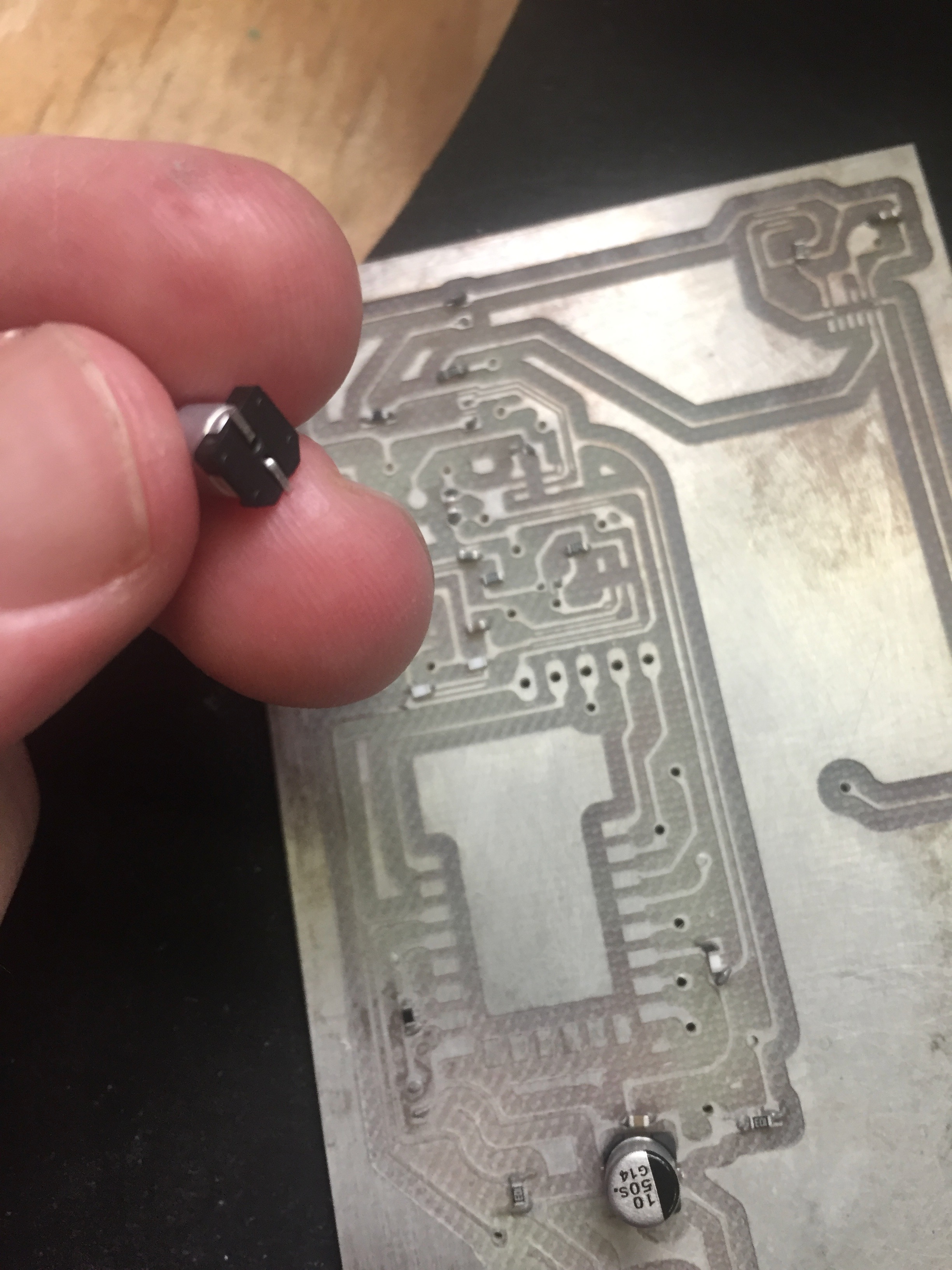
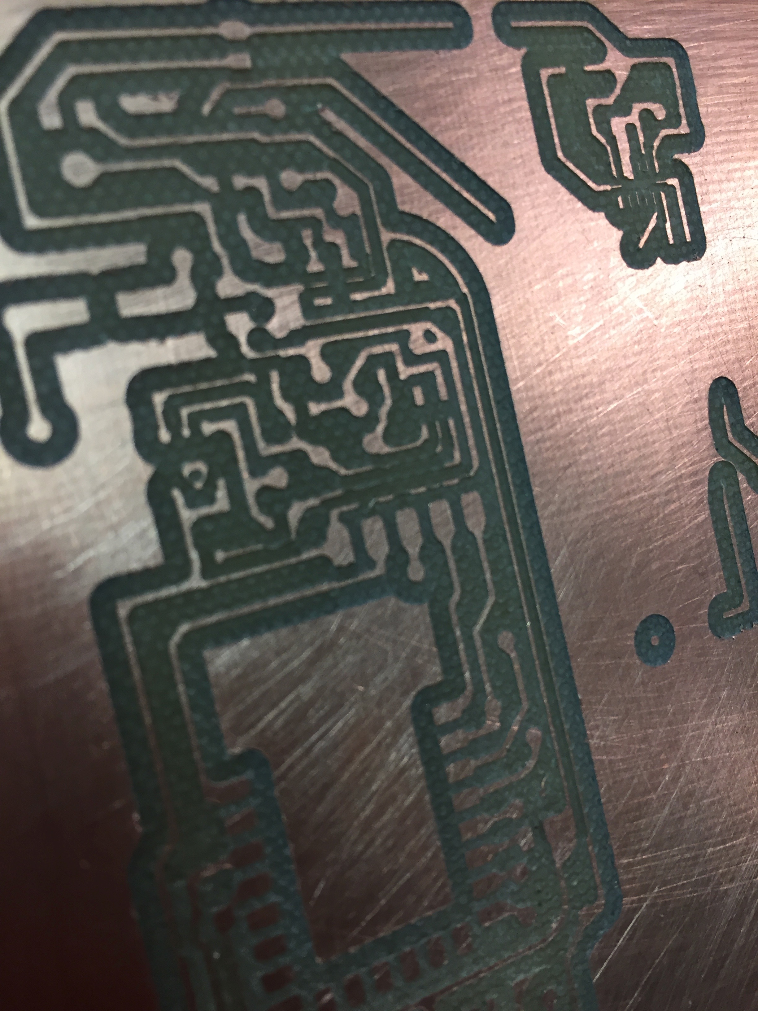
(3)

Most recent board with caps in the wrong spot. Added more lines in for cutting. Unsure why the bantam didn’t lift in between cuts on the dimension layer though.
Parts Testing:
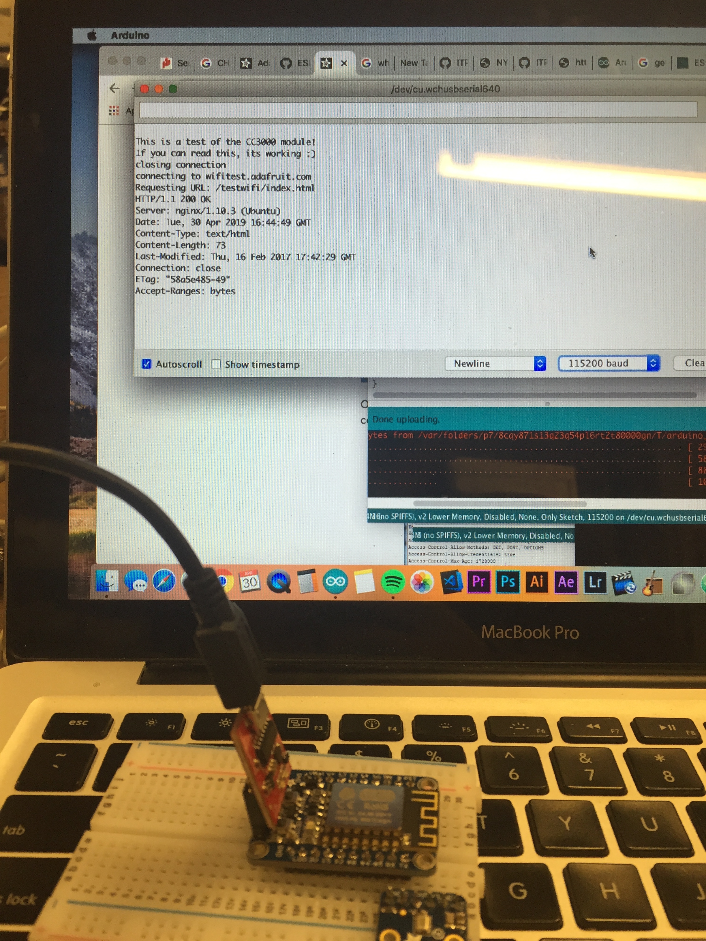
got the mac address set up

Blinking light test shows code and libraries I have on my comp are correct

Audio test shows code and component working

Touch test shows code and component working
Accelerometer test shows code and component working (together with touch sensor!)
Circuit Diagram

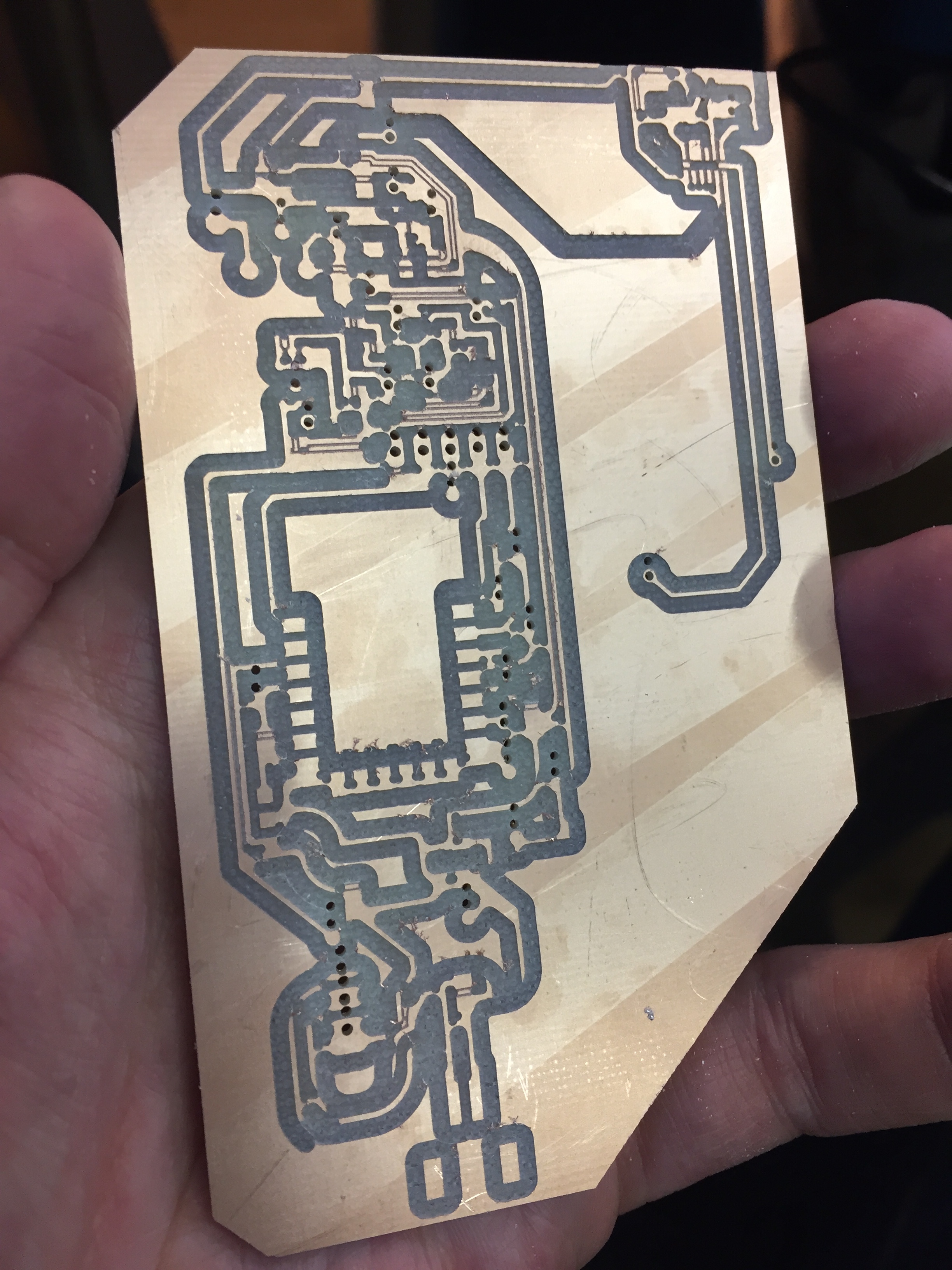
Board Fab:
Had some initial errors with board fab but they were fixed on second pass… or so I thought.

Used liquid tin in the morning thinking it was going to be nice and quick… nope!
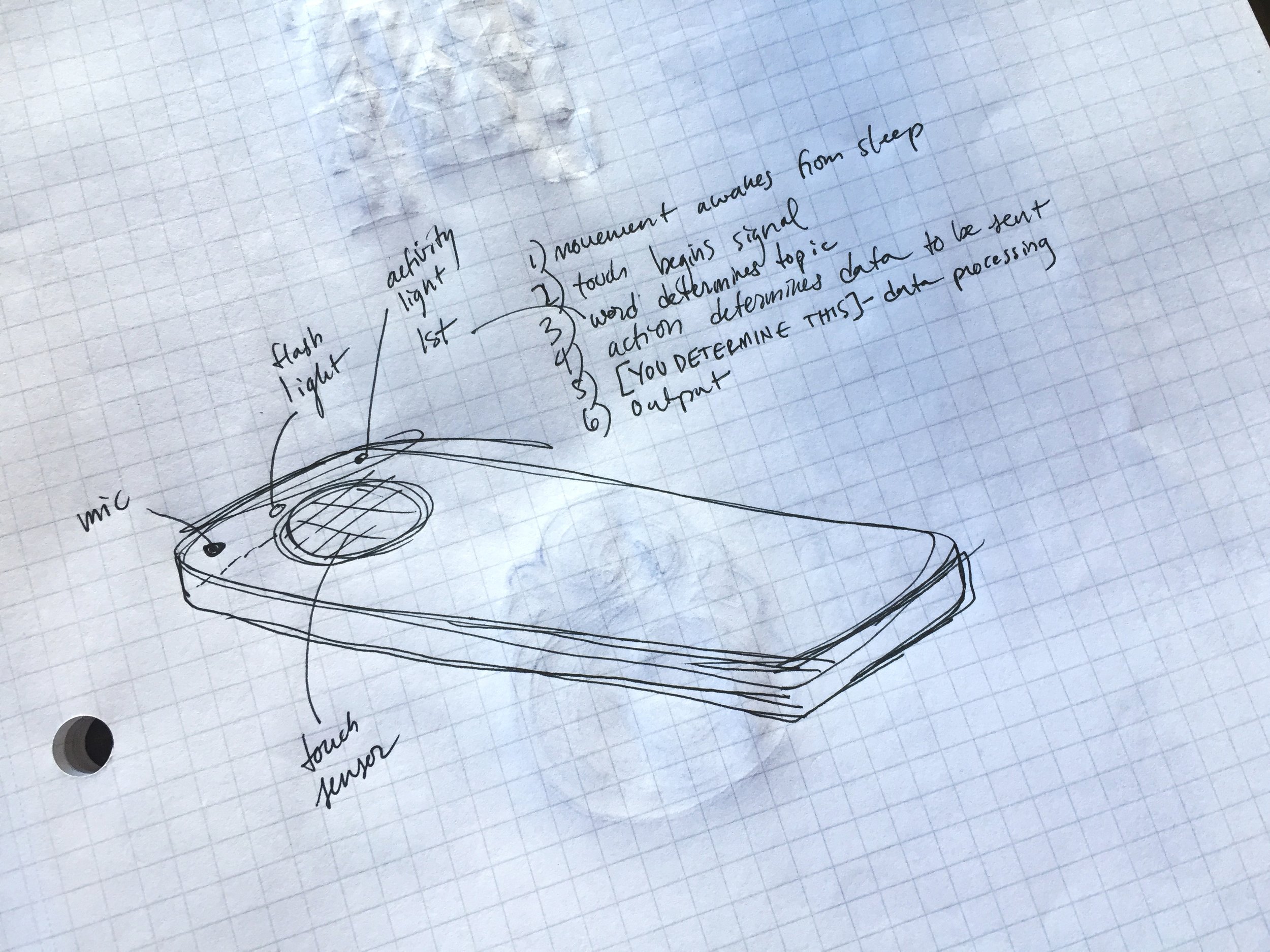
Enclosure plans:


The final board looks so good! But actually the large cap pads are in the wrong spot - they should be in the 10 and 22uF spots (3), not 100 and 220pF spots (2). I’ll need to mill again :.(
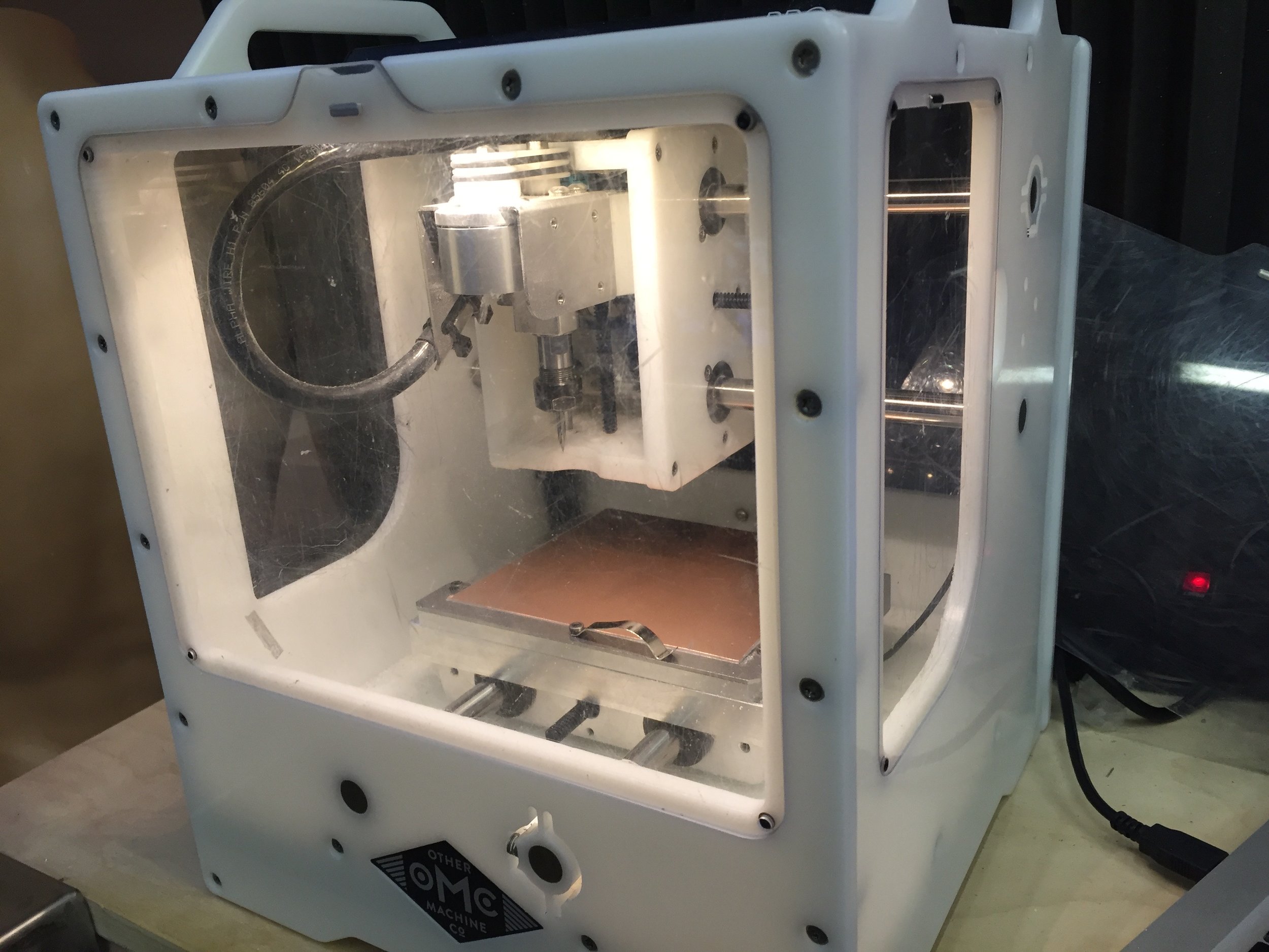


This is where I started to learn a bunch more about the Bantam. As in.. the errors really started to occur. I realized my packages were too big for my board. Then I noticed my board traces were too thin. Then I couldn’t figure out why the thing said no window on when all windows were on (the back one wasn’t actually). Then my comp died and had to be restarted mid job. In total this 4 hours meant I went through 4 boards only to be left needing to do more. My parts didn’t arrive, and I broke 2 bits. Great evening.
